

Maintaining Water Cooled Chiller Efficiency
 Maintaining chiller plant efficiency depends on a wide array of factors. However, if you’re looking to keep performance on the right side of the chiller efficiency curve, then you need to follow these tips:
Always maintain a daily operating log of the chiller
As a chiller operator, it is essential that you document the performance of your chiller on a daily basis with a detailed and highly accurate operation log. This log will help you in your aim to compare the performance of the chiller with design and start-up data and it will also help in detecting any issues that might arise, such as lags and inefficiencies in control set points. Also, this process will give you the freedom and opportunity to gather a list of operating conditions, and these conditions can in turn be analyzed and reviewed with an aim of curbing lags and maintaining chiller plant efficiency.
For instance, if you notice a slow but consistent increase in the condensing pressure within a month, then it will be much easier for you to systematically check ad correct the possible reasons for the advent of this condition by simply making a reference to your log book (by the way a few reasons for this can include fouled condenser tubes as well as non-condensables).
Upon request, it is possible for manufacturers of chillers to provide a list of recommended data points that are specific to an equipment. This means that operators can take date readings on a daily basis, once in a shift at around the same time. Chillers that are manufactured today are usually controlled with the use of microprocessor controls, so it is possible for managers to automate the process with the use of building automation systems that are controlled by microprocessors.
Ensure that you keep the tubes clean
Over the past few years, it has been discovered that one of the biggest potential hindrances to the desired performance of chillers is heat transfer efficiency. Maintaining chiller plant efficiency and optimal performance are directly relative to the ability of such a chiller to transfer heat, and this begins with that chiller having a clean evaporator and a set of clean condenser tubes. Larger and bigger chillers usually have several miles of tubing in their heat exchangers, and if you are to maintain optimal chiller plant efficiency, it is essential that you to keep these surfaces clean.
When chillers are in operation, it is pretty easy for contaminants made of a wide array of materials (such as mud, sludge, algae, scale etc.) to accumulate on the waterside of these heat transfer surfaces. When this happens, the tubes become fouled, and this means that maintaining chiller plant efficiency in general is deteriorated a great deal. The rate at which this fouling occurs depends a great deal on the type of the system- whether it is open or closed- as well as the water quality, its overall cleanliness, and the temperature of the water as well.
A majority of chiller manufacturers will recommend that you clean these tubes on an annual basis (since they are essentially part of an open system) and for the evaporator tubes, they usually recommend a cleaning at least once every three years (for closed systems, that is). However, if the evaporator is part of an open system, then periodic cleaning and inspection are both required to ensure the cleanliness (and in turn, effective and optimal performance) of the chiller.
When it comes to cleaning tubes, there are usually two primary methods that are open to managers:
Mechanical cleaning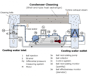
The mechanical cleaning method helps to remove sludge, algae, mud, and loose materials from smooth-bore tubes. Under this form of cleaning, the steps involved include removing the water-box covers, giving the tubes a thorough brushing, and flushing them completely with clean water. However, if you manage an internally enhanced tube, make sure to consult the manufacture of the chiller for recommendations regarding mechanical cleaning.
Chemical cleaning
This form of cleaning also deals with the removal of scale. It is recommended by most chillers that you consult with a local water treatment supplier in order to determine the proper cleaning solution that is needed. However, you should also know that after chemical cleaning should ideally come a thorough and comprehensive mechanical cleaning.
The newest brand of chillers also come with automatic the brushing systems that can be retrofit to be used in existing chillers. Tube brushing systems make use of small brushes with nylon bristles that flow through the tubes in order to get them cleaned. Also, a custom made, four-way reversing valve is installed in the piping system of the condenser and every six hours, the flow is automatically reversed by the system though the condenser tubes for a total period of about 30 seconds.
Along with a proper and effective water treatment, these systems will be able to properly eliminate fouling within the chiller and maintain desired temperatures, all of which will result in high efficiency chillers.
 Ensure that the unit is as leak-free as possible
If you are to get a high efficiency chiller, manufacturers recommend quarterly tests of compressors for leaks. Low-pressure chillers using either CFC-11, which has been phased out, or HCFC-123 have sections of their refrigeration systems that operate at sub-atmospheric pressure.
Although these chillers are the most common in today’s facilities, it is difficult to create a perfectly sealed machine, and leaks allow air and moisture, commonly referred to as non-condensables, to enter the unit.
Once in the chiller, non-condensables become trapped in the condenser, increasing condensing pressure and compressor-power requirements and reducing chiller plant load efficiency and overall cooling capacity. Low-pressure chillers have high-efficiency purge units that remove non-condensables to maintain design-condensing pressure and promote efficient operation. One chiller manufacturer estimates that 1 psi of air in a condenser equates to a 3 percent loss in chiller plant efficiency.
Moisture in a chiller also can create acids that corrode motor windings and bearings and create rust inside the shell. Small rust particles called fines float in the vessels and get trapped inside heat-exchanger tubes. Fines on tubes decrease the unit’s heat-transfer effectiveness and overall efficiency. Left unchecked, they can lead to costly tube repairs.
The best way to monitor leaks in a low-pressure chiller is to track purge-unit runtime and the amount of moisture accumulation at the purge unit. If either of these figures is too high, the unit has leaks. Other indications of air in the system include increased head pressure and condensing temperature.
High-pressure chillers using CFC-12, HFC-134a, or HCFC-22 operate at pressures well above atmospheric pressure, and leaks in these types of chillers release potentially hazardous refrigerants into the environment. Environmental regulations limit the amount of annual refrigerant leaks.
Leaks will also result in a lower refrigerant charge as well as other operational issues (including but not limited to lower evaporator pressure, which in turn can cause the compressor to work even harder in order to produce a lower cooling capacity). For positive pressure chillers, technicians should keep track of the charge level of the refrigerant as well as the evaporator pressure this is to detect leaks and find solutions as soon as possible.
Sustain the proper treatment of water
Most chillers use water in the transfer of heat, so you need to ensure that the water must be properly treated in order to prevent scale, the growth of biological organisms, and corrosion. If you’re using a closed water system, then all you need is a one-time chemical treatment. These are definitely typical of chilled-water systems connected to the chiller evaporator.
Open systems are usually used for condenser-water systems that are in one way or the other connected to the chiller condenser. Condenser systems that make use of sources such as cooling towers will require continuous chemical water treatment in order to sustain the purity of water.
As a manager, you need to work with a chemical treatment vendor that has a proper knowledge of local water supplies and who will be able to provide a full-service maintenance for all facility water systems.
Note that if the vendor is able to maintain a proper chemical treatment of the evaporator and condenser-water systems, then there shouldn’t be too much of a problem with scale. When there is scale present in the condenser or evaporator tubes, this indicates that the water has been treated poorly. The vendor needs to conduct a test of the water quality on a quarterly basis (every three months) and correct the water treatment program. By doing this, the cleaning of the chiller tubes will be easier, and the performance of the chiller in general will definitely be enhanced to a great deal.
Also, it is important that you clean all systems strainers every three months as well. Sand filters and side-stream filters for the condenser-water systems are very effective means of maintaining clean water, but their efficiency will depend largely on how well they are maintained as well. In order to determine the point when cleaning is required, technicians are required to monitor drops in pressure at the filters and when it is time for cleaning, they should also make sure to refer back to manufacturer recommendations in order to ensure that they don’t get the cleaning process wrong. Regular cleaning is required for filters, regardless of the drops in pressure.
The proper maintenance of trainers and filters will put a limit on the erosion of the chiller tube; a phenomenon that is caused by the movement of sand or other particles and impurities at high velocities. This erosion and tube pitting will decrease the overall effectiveness of the heat transfer process, which in turn will reduce the efficiency of the chiller in general. Also, if they go uncorrected, it is highly probable that these phenomena will lead to plugged tubes or very serious tube failure.
Technicians should conduct inspections of chilled water and condenser water piping systems on an annual basis in order to inspect for any evidence of corrosion and erosion. Most manufacturers will recommend the eddy-current inspection of heat exchanger tubes, as well as an electromagnetic procedure that will help to evaluate the thickness of the tube wall. These should be conducted once every three to five years.
Conduct an analysis of the oil and refrigerant
Conducting a chemical analysis off oil and refrigerant can also help you to detect issues that contribute to the contamination of the chiller before they become even much worse. The testing process consists of a spectrometric chemical analysis that will help to determine contaminants such as acids, moisture, and metals. All of these have their ways of hampering efficiency and performance, so it is essential that you get them checked. The analysis must also be performed by a qualified chemical laboratory that specializes in HVAC equipment. A vast majority of manufacturers also provide analysis services for oil and refrigerant on an annual basis.
While the chiller is operating, the technicians should take an oil sample. Keep in mind that the oil should only be changed if the oil analysis indicates so. The technician should also ensure to keep tabs on oil filters in order to notice any drops in pressure and change them during a recommended oil change or if pressure drop is outside a range of tolerance.
The oil analysis process is capable of helping to detect any issues with the chiller. For instance, when the oil has a high moisture content, it is a signal to the fact that there is an issue with the purge unit. Also, changes in the characteristics of the oil can point to the development of compressor wear; something that you just cat afford to have in your chiller.
Managers are able to make use of refrigerant testing in an aim to determine contaminants that might lead to a wide array of issues with reliability and efficiency. One of the major contaminants is oil, and it migrates into the refrigerant. One chiller manufacturer estimates there is a 2 percent loss in chiller efficiency for every 1 percent oil found in the refrigerant, and it is not uncommon to find 10 percent oil in older chillers’ refrigerant. Based on this estimate, such contamination can lead to a substantial 20 percent decrease in efficiency.
The chiller efficiency calculation formula
If you’re looking to calculate the efficiency of a chiller, you use the COP (Coefficient of Performance)
The proper chiller efficiency calculation formula is the ratio of the refrigeration effect produced by the chiller as against the amount of electrical energy that the machine used to produce it.
Both units are measured in Kilowatts (kW)
The COP of centrifugal chillers is depicted by a tool called the centrifugal chiller efficiency curve.
Calculation for maintaining chiller plant efficiency
Water-cooled chillers make use of various types of air conditioning. Maintaining chiller plant efficiency calculation is determined by the electrical engineering air conditioning concept (measured in Kw/hr.) to energy moved (measured in Tons or Btu/hr.).
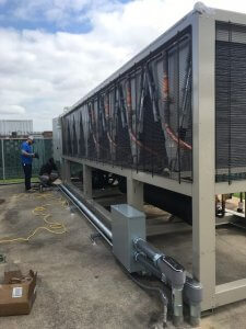
Installing a Water-Cooled Chiller
A few highly essential parts of the water chilled cooler include:
- Evaporator: During the operation of the unit, the job of the evaporator is to maintain low temperature and pressure. This will help for the evaporated refrigerant to take the heat of the cooling water away.
- Condenser: During the operation of the unit, the high pressure and temperature will be maintained by the condenser so that the heat of the refrigerant will be taken away by the cool water that flows through the condenser.
- Screw compressor: The screw compressor will push the evaporated refrigerant in the evaporator to the condenser. It will also keep the pressure of the system.
- Oil separator: This will separate the gassy refrigerant from the refrigeration oil and have the latter sent back to the compressor so as to ensure the proper and safe running of the compressor.
- Electric control system: Through the adoption of microcomputer control system, it is possible for you to adjust the output cooling capacity so as to properly meet the needs off the user. You can make use of side, heat source water pump and a cooling tower fan.
Installation Environment
- Ensure that the unit is not too close to tinder and fire. If it is installed with the heating unit, you will have to consider the effects of thermal radiation
- Ensure that the site is one that is drafty and where the indoor temperature is below 45℃
- Make sure that the site has less dust
- The site should also be bright, so as to make it easy for inspection and maintenance purposes.
In order to meet the maintenance, operation and inspection needs of the heat exchange tube condenser and the evaporator and is drafty. It is not permitted to install and store the unit outside or if you need to ensure proper space for tubing. This space should be as long as both the condenser and the evaporator.
To make it easy to lift and overhaul, make sure to install a derrick car or a traveling crane. For the sake of easy lift and overhaul, it is necessary to install traveling crane or derrick car and ensure that the machine room is high enough.
There should be a complete draining of the surrounding of the unit as well as the whole machine room.
The chiller part load efficiency consideration
The load that is put on the cooling equipment usually decrease with a decrease in the outdoor air temperature. This phenomenon ends up decreasing the chiller plant efficiency as well. The colder outdoor air will also provide a heat sink for the cooling equipment, and that can increase chiller plant efficiency.
However, in most cases, the second scenario is more pronounced.
Site Confirmation
In order to perform the installation in a correct, fast and safe manner, make sure of the following:
Installation site
Confirm that the installation site is in accordance with the requirements of the chiller itself.
- Hole for carrying: Confirm the perfect size, height and lifting volume. Also, make sure to remove any obstacles.
- Order of carrying: Have a determined way and the order of carrying
- Access for carrying: To provide for proper access, have any obstacle on the path removed.
Base Construction
The parts of the crew compressor are less movable and also stable, so the load of the base is small. In the case that there is any corrosion in the unit footing, it is essential that you make sure the entire surrounding of the unit is in good drain. Also, the basic plane to base steel of the unit should be smooth as well.
- In case of corrosion of the unit footing, it is required that the surrounding of the unit is in good drain state. The corresponding basic plane to base steel of the unit should be smooth. The specific requirements are as below:
- The maximum difference in altitude (levelness) should be within 3mm.
- In order to provide for easy maintenance and inspection of the refrigerant unit, the base should be higher than 100mm
- You will also have to install a drain ditch around the refrigerant unit.
- There should not be any space between the foot plate of the refrigerant unit and the base steel
- The installation base of the unit must be concrete or of a steel composition so as to ensure that it will be able to bear the weight of the machine while running. Also, the top should be horizontal. It is better to prepare a drain ditch in the installation base
Carrying
Inspection of the unit: Before the unit is unloaded, make sure that you conduct an inspection of the appearance and accessory of the unit; if it is damaged, let the transportation company know and look into assessments and ways that you can remedy the situation.
From there, also take an assessment of the quantity according to the packing list; check whether there is any piece that is missing (such as spare pieces and spare parts). If there is any lack of part, speak to the manufacturers
Product model, parameter and production date are shown on the nameplate. Please check whether they conform to the contract or related technical decrements.
Lifting
- The lifting position is marked on the unit. After confirming the installation of base, shock pad and foundation bolt, place the unit on the shock pad with strong sling (strong enough to bear the weight and impact of the unit during lifting) via the crane.
- During lifting, in order to avoid damaging connectors of the unit, please lift the unit in strict accordance with the lifting marks.
- Do not enlace the compressor, shell and tube exchanger with slings. Do not lift the unit with bolt hole. Avoid sloping lifting.
Installation
- First of all, check whether the base conforms to the footing size of the unit in the general diagram. The base should be smooth and level.
- Put the base steel in the prescriptive position.
- Put the refrigerant unit on the base steel.
- There should be no space between the base steel and body foot plate of the refrigerant unit. Adjusting shim should be put between the base steel and the concrete foundation. Adjust the base steel to be level (the altitude difference should be within 0.5mm every meter)
- Lift the refrigerant unit and put the damper rubber blanket on the base steel, and then put the unit on the damper rubber blanket.
- After installation, ensure that the horizontal slope should be within 1/1000. If it is beyond the range, adjust the unit. Put a pad (the pad is provided by the installer) between the footing and the shock pad, and then check the horizontal slope until it is passed
Piping
- After leveling the unit, connect the chilled water pipe and cooling water pipe. Piping should have flexible parts and independently supportive capability to avoid any distortion or vibration. The pipe should be supported and correctly joined. Shock pad can be added to the pipe supporter so as to reduce the vibration.
- There are marks near the inlet and outlet for reference when connecting the pipe. It is necessary to connect the pipe according to the marks on the unit.
- Connect the pipe for cool water and cooling water (flange or clamping band connection) and set a filter in the inlet. Whether the pipe is horizontally or vertically led from the unit to the water pump is decided by the user based on the site condition. Manometer should be set on the inflow pipe and outflow pipe of the unit so as to measure the differential pressure of the inlet and outlet and thus estimate whether the water flow conforms to the rated water flow. The control valve of cool water and cooling water must be installed on the outflow pipe of the refrigerant unit to avoid disorder of the water flow as well as eroding the heat transfer tube near the inlet.
- When the water quality is bad, there will be much deposit such as scale and sand in the shell and tube exchanger, which will decrease the water flow and affect the rate of heat exchange. Meanwhile, if the quality of chilled water and cooling water is bad, it will not only cause scaling, affecting the rate of heat exchange and the performance of the unit, but also cause erosion of the heat exchange pipe which may lead to serious leak. Thus, the water must be filtered and softened by the water-softening equipment before flowing into the system. If the water quality is too bad, have t treated accordingly.
Wiring
Before electrical installation, ensure that the general power supply is cut and have the sitch cabinet installed in a suitable position.
- Have the main power cord and the Earth wire connected to the electric circuit through the service entrance. Make sure to cut off the general power supply and install the switch cabinet in the suitable position.
- Connect the main power cord and the earth wire to the electric control cabinet through the service entrance. Connect the wire to the corresponding wire holder and earth wire holder. It is a must to ensure the correct connection of L1,L2,L3.
- Ensure that the voltage fluctuation of main power supply is within ±10% of the value shown on the nameplate and that the voltage unbalance is within ±2%. If it exceeds this range, stop the unit and contact with the electric department. The formula of calculating voltage unbalance: voltage unbalance%= maximum deviation from average voltage / average voltage×100%
- Before connecting wire of main power supply, check the phase sequence of each power cord.
- Connect the control circuit
- Connect the control wire of the AC contactor in chilled water pump, cooling water pump and cooling tower with the flow switch and the electric control system.
- The unit must be energized 8 hours before running of the unit and should be kept energizing in working seasons so that the heating tape of the compressor can heat without running of the compressor. In that case, the liquid refrigerant gathering in the compressor will evaporate and avoid damaging the compressor.
- Ensure the unit is earthed reliably.
- Inlet wire of electric control cabinet. A dismountable square sheet-metal piece is fitted in the inlet of electric control cabinet. When installing, please remove the sheet-metal piece and hole it according to the size of cable terminal. Lead the cable through the hole and fix it.
Efficient Chiller Designs
High efficiency chillers owe their efficiency in large part to the effectiveness of their designs.
So, lets take a look at some of the most effective types of chiller designs:
Electric Motors
The electric motor is definitely the most popular chiller compressor drive. Most of them are usually fixed motors. Since the power requirements of compressor are usually proportional to the difference between the pressures of the evaporator and condenser and the refrigerant flow requirements, there is an according variance in motor loads. Load variations are handed by the cylinder unloading as well as multiple compressors staging for various units, side vane capacity control (for screw compressors), and inlet guide vanes (applicable for centrifugal compressors).
In cases where you might be able to get a better way to module compressor capacity and performance by changing the compressor speed, it is recommended that you make use of a variable speed electric motor. New chiller installations hardly make use of this approach due to the fact that it is no possible for chiller manufacturers to build in excellent modulation control. The application of variable speed motors has mostly been inn retrofit applications.
However, you need to be careful and always consult the machine manufacturer for product warranties and performance verifications before embarking on a project to modify an existing chiller.
Steam Turbines (Back Pressure & Condensing)
Steam turbines, reciprocating engines, and sometimes gas turbines are used to drive chiller compressors. The most common applications are very large (over 1500 tons) steam turbine-driven centrifugal chillers used in cogeneration applications for large hospitals or industrial cooling. In situations where electrical demand charges are high (say over $25 per kW per month) or where a demand ratchet could make an electric-driven chiller too expensive to operate for a few months a year, steam turbine-driven chillers are often specified.
So why not reciprocating engines or gas turbines?
Steam turbines use the existing boiler system, so they don’t have to worry about fuel supply or air emissions. Since the steam needs of the site are usually dictated by the colder months, the existing steam generating capacity is often more than adequate to support cooling. Plus, the operating and maintenance characteristics of steam turbine-driven chillers are much better than reciprocating engines or gas turbine-driven equipment. Finally, where existing boiler capacity is adequate, steam turbine-driven chillers cost less than reciprocating engines or gas turbines. There are two basic steam turbine designs: back pressure and condensing. These indicate whether steam leaving the turbine goes on into the steam distribution system to satisfy process or heating requirements (this is “back pressure”), or whether the steam leaving the turbine goes straight to a dedicated steam condenser where it is rejected via a cooling tower or river water.
Logically, condensing steam turbines are more expensive and less efficient than the back-pressure designs.
When site steam requirements are reasonably steady and in excess of the steam flows necessary to drive the chiller, the back-pressure design makes the most sense. Where this is not true, and power costs would be high for an electric-driven machine, a condensing steam turbine may be the most cost-effective alternative. In many cases where steam turbines are considered, rather than apply them to a chiller operating relatively lower hours a year, the turbine is typically used to drive a generator to take maximum advantage of its power generating capabilities.
Selecting a chiller design like this requires careful consideration of site-specific conditions. Steam turbine driven chillers represent a complex design in any situation. It is wise to consult with qualified design professionals and reputable equipment manufacturers before making a final decision.
Reciprocating Engines
Designers usually make use of reciprocating engines to drive chillers in the smaller range. The compressor, which is usually a screw or centrifugal model, is usually coupled directly to the drive shaft of the engine. Engines are usually considered when the site is able to make use of the energy in the hot water or hot air exhausts that are produced. Compression power is generated through the conversion of about one-third of the total fuel input. Therefore, the effectiveness of the reciprocating engine will most probably depend on how cost effective the heat recovery is. Engine jacket water can easily be recovered, and it also represents a significant percentage of the fuel input. Another significant aspect of the fuel input is the heat from the engine exhaust, although it is not possible to fully recover this heat.
It is best to determine the cost effectiveness of the engine-driven chiller with the use of a cautious assessment. This assessment must put the following factors into consideration:
- The heat recovery that reflects the actual site-specific heating needs
- The conservative annual heating requirements
- The realistic costs of operation and maintenance. These costs are usually higher than those of any other mechanically-driven chiller alternative
Once the realistic heat estimates have been put into the equation, the only issue that needs to be conquered is that of the O&M expense. Here, the usual number used is $0.01 per ton-hour more than that of an electric chiller design. Make sure that you always rely on the services of qualified design professionals and resected manufacturers of equipment when looking for estimates of operating cost, installed cost and performance.
Gas Turbine Designs
It is very rare for people to choose gas turbines to drive chiller compressors as the efficiency of the cogeneration system that makes use of a gas turbine will rely a great deal on the ability to recover the waste heat of the engine. In cases where it is possible to use the heat, the gas turbine is ideally used as a means of driving a generator in order to take maximum advantage of its ability to generate power. The major issues usually encountered with the use of gas turbines as chiller drives include the fact that gas turbine power levels (as well as the water production that results) are greatly reduced (~ 25-35%) at levels where the ambient temperature is high. This means that at the time when the site will be in need of maximum power so as to drive a chiller compressor, the gas turbine will not be able to deliver the required power.
One solution to this issue might be to make use of some of the chilled water in production to cool gas turbine inlet air. However, this will also have a negative effect on net chilled water production.
Operating and maintenance procedures are also pretty sophisticated. It is essential to protect the engine from inlet dust, frosting, contaminants, or damage resulting from the presence of foreign objects. When placed in the hands of highly qualified and experienced personnel and run continuously, it is possible for a gas turbine to record extremely high annual availability and very low costs of maintenance. Unfortunately, though it is rare for chillers to run continuously.
If you use natural gas to fuel the gas turbine, pressures of the gas will have to be higher that as it is with any other mechanical driver. These pressures might not be available from suppliers, and this means they will most probably need a supplemental gas compressor. However, this gas compressor is usually pretty unreliable, and this means that you’ll need to add a spare to the system design. All of this makes this design attribute pretty expensive. In addition to the power that is used to compress thee natural gas fuel input, the compressor will become an important aspect of the cost-effective equation.
However, all of this is not to say that the gas turbine is a terrible choice for a mechanical drive application. It is just a pointer to the primary concerns that the designer and owner should consider when evaluating the options. A high efficiency chiller can still be achieved with this turbine, but it might come at quite a lot of costs to the owner.
Therefore, due to the cost implied by the gas turbine, its operational characteristics, and site-specific estimates, it would be a wise decision for you to ensure that the installation is done by qualified design professionals and the highest quality of materials.
If you would like your chiller reviewed give us a call at (225) 925-5236.


